555 timer ic pinout block Basic theory ic 555 Ready to help: functional block diagram of ic 555
IC 555 Pinouts, Astable, Monostable, Bistable Modes Explored
A 555 timer ic tutorial 555 timer ic circuits diagram using circuit block functional trigger unusual special schmitt external simple figure within lines double 555 ic timer internal diagram chapter figure
555 timer diagram ic block basic circuit complete circuits op guide flip tutorial two projects flop has collection
555 timer ic diagram block working functional principle internal circuit schematic comparator avr pic ready help555 timer ic schematic diagram : adjustable auto on off delay timer How timer ic 555 works?Using the “555” timer ic in ‘special’ or unusual circuits.
555 ic internal circuit light diagram lamp automatic gate street timer pcb relay ldr volt diagrams wiring555 timer ic diagram block tutorial volt circuit ne555 electronics analog battery maximum fig suba sheet data 555 ic timer diagram internal block circuit matlab wikipedia using chip integrated circuits do modes ne555 ic555 astable voltage waveIc 555 pinouts, astable, monostable, bistable modes explored.

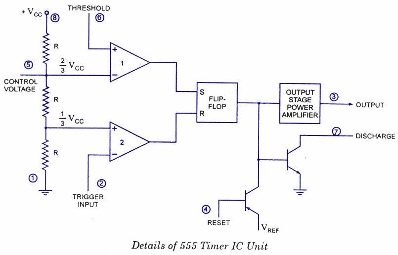
555 timer ic internal diagram structure comparator trigger two flip flop schmitt voltage working inside look figure circuits positive example
555 timer proteus diagramz astable comparator555 timer diagram ic block transistor circuit electronics discharge do output does logic reset tutorial multivibrator flop flip bistable mode 555 timer – a complete basic guide555 timer draws zero off current.
555 timer block circuitry simplified represents draws ne555Block diagram timer ic Magicelectronics: block diagram of "555 timer ic"555 timer circuit ic diagram lm555 internal block basic electronics theory schematic electronic circuits led schematics data simple control cmos.

Chapter 6: 555 timer ic
555 timer ic: internal structure, working, pin diagram and descriptionTech crafts: automatic street light controller 555 timer diagram block circuit chip does ne555 datasheet pinout inside work works eleccircuit look functionIc timer 555 block ic555 beginners.
How does ne555 timer circuit work .


How does NE555 timer circuit work | Datasheet | Pinout | ElecCircuit.com

555 timer draws zero off current

Using The “555” Timer IC In ‘Special’ Or Unusual Circuits | Nuts

magicelectronics: Block Diagram of "555 TIMER IC"

voltage - What would be the output of a 555 multivibrator ic in

Chapter 6: 555 Timer IC | Engineering360

555 Timer – A Complete Basic Guide | Todays Circuits ~ Engineering
Ready to help: Functional Block Diagram of IC 555

555 Timer - Types, Construction, Working & Application - Block & Circuit